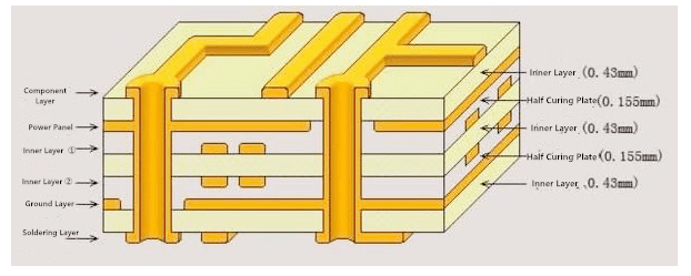
Multilayer Printed Circuit Board

Multilayer printed circuit boards are used in various types of electronic devices. These include single panel, flex circuits, and cascade structure.
Cascade structure
Printed circuit boards, referred to as PCBs, have been used for years as a medium for electrical engineering. They consist of many conductive and insulating layers. The layers are usually laminated onto a nonconductive substrate. In a multilayer printed circuit board, there are more than three conductive graphics layers and more than three insulating layers.
Multilayer boards are also known as sandwich plate structures. These boards have been produced by different techniques. One common way of making a sandwich plate is by using a single panel. Another method is by making a double panel. Often, a single panel can be created by combining two or more layers of copper.
Using more than three signal layers isn’t recommended. That’s because it can cause issues with wiring between components. However, the proper number of signal layers can enhance the signal integrity of the final product.
Some of the benefits of a multilayer printed circuit board include lower EMI and higher reliability. But a more complicated design requires more attention to the details. Moreover, manufacturers have to take into account the demand for their products. Hence, they are advised to analyze the wiring bottlenecks before they choose their layout.
A good multilayer PCB layout brings power and ground to the back of the board. It is important to prioritize the connections to the power supply. Similarly, the spacing between the power cords and signal lines should be more than 20 mil. And it is often better to use the same type of components, so that the wiring is consistent.
A cascade structure on a multilayer printed circuit board is an optimal arrangement. This is a combination of the three layers and a few special features. For instance, there are internal layers which improve signal frequencies and decrease EMI. Also, there are some internal layers which serve as a ground plane.
Lastly, there are some internal layers which provide electrical interconnection. If the board is being designed for high-speed signals, the signal transmission layer needs to be located between the two layers of electricity.
Despite the complexity of the design, a properly implemented cascade structure is the best choice. However, it is also important to consider the symmetry requirement.
Single panel
Printed circuit boards are used for assembling electronic devices. They are made of two or more copper layers, usually sandwiched in between other layers of substrate. This allows for high component density, lower EMI and improved signal integrity.
Several small printed circuit boards can be grouped together for processing as a panel. The layout and design of the PCB depends on the circuitry that is to be used.
A multilayer PCB is typically composed of more than three layers of conductive graphics and insulation. These layers can be made of copper foil laminated technology or single chip laminated technology.
Multilayer PCBs are commonly used in high speed electronics applications. They are also more efficient than double plate PCBs. But their production cost is higher. So manufacturers must consider all aspects of demand and costs.
To improve anti-jamming performance, a PCB multilayer printed circuit board may be designed with a sandwich plate. An important advantage of a sandwich plate over a conventional double panel is that it can suppress multiple single plate.
The layer number of a multilayer board depends on the power supply. It is important to determine the appropriate wiring scheme for the power and ground network.
Circuit traces on the inner layers will take up too much surface space if they are not surrounded by adjacent substrate layers. Therefore, a designer must commit to the minimum line length.
The wiring scheme of a PCB should be analyzed by an experienced designer. Ideally, the wiring should not be parallel. However, if the design requires it, a reasonable arrangement of lines can reduce the sources of interference.
There are also other factors to be considered when analyzing a PCB wiring scheme. Some of the most important factors are the power layer, the signal layer, the electrical layer and the power cord. Each of these layers has its own unique needs and requirements.
In order to minimize power resistance, a layer of copper film is often used between the inner layers and the power or ground network. This can reduce power resistance significantly.
Similarly, an electrical layer can help provide shielding. And, an electrical layer can also reduce the amount of electromagnetic energy absorbed by the board material.
Electrode layer
If you want to make a multilayer printed circuit board (PCB), you need to consider the electrical layer. It helps to shield and decouple power supply and ground, which in turn enhances signal integrity and reduces EMI.
The multilayer PCB has many layers that must be aligned in a precise manner. This can be done with the help of the Layer Stack Manager in the PCB editor interface.
You can set the insulating Gap width and the Track Width to suit your needs. A larger Track Width is useful to set the distance between layers. However, the width should be no more than about 40 mill.
Another good idea is to sandwich a high-speed signal transmission layer between two electrode layers. Putting the copper film layer in this manner can also improve the anti-interference performance of your circuit.
The next step is to set the appropriate properties for the electrical layer. This is usually a whole sheet copper film. When you open the Settings dialog box, you will find the Electric Layer Division option. Select this and you will be presented with a cross shape that shows the split planes for the network.
Now you need to decide which layers should go where. There are many options that you can choose from. Choosing the right ones is a matter of weighing the advantages and disadvantages.
For example, if you want to use a high-speed signal line, you should make sure it is located on a layer with a large area of copper film. The copper film will help reduce power equivalent resistance and grounding impedance.
The smallest signal in the universe can be represented by a trace on a signal layer. This is equivalent to a resistor of a smaller size.
In a similar fashion, the largest voltage gradient material can withstand is determined by the dielectric breakdown voltage. This is a fancy word that refers to the amount of voltage a material can withstand before it breaks. Generally, the dielectric constant is dependent on the frequency of the signal.
In addition to the above methods, there are also other ways to segment the electric layer on a multilayer PCB.
Flex circuits
Flex circuits on multilayer printed circuit boards have a number of advantages over rigid PCBs. They are more flexible, more space-efficient and can be bent in any shape. This type of PCB is also more efficient in assembly, which means less cost and more time for the manufacturer. It has excellent heat dissipation and signal integrity.
The flex circuit’s internal layers are made of bare copper traces, and the outer layer is a polyimide film. Adhesive is used to bond these two materials. Polyimide has a low coefficient of thermal expansion and provides comprehensive temperature resistance.
Flex circuits have a wide range of applications, ranging from bar code equipment multilayer printed circuit board to medical treatment, satellites, and power generation. Some of these applications include industrial control, data communication, and optical networking. Unlike rigid boards, flexible PCBs are more robust, requiring fewer parts and reducing assembly errors. These features are important to designers who want to reduce the size and weight of electronic packages.
Besides their flexibility, flex circuits are able to handle controlled impedance. The speed at which electricity travels down a trace affects the impedance. In order to improve the impedance, a flex circuit can be routed in perpendicular directions. A perpendicular route is advantageous to the malleability of copper.
The final residual material should be greater than the minimum distance between the exterior edges and non-plated interior through holes. This helps the adhesive flow, minimizing the risk of adhesive damage.
The most common dielectric for a flex circuit is a polyimide film. There are other options, such as specialty metals for certain applications.
Besides the ability to be shaped, flex circuits on multilayer PCBs offer a higher heat transfer and mechanical resistance than rigid boards. This makes them a good choice for high-density products. EMI shielding is also possible with a flex PCB.
Multilayer flex circuits are a great option for many design challenges. Although they are more expensive, they are often a better solution than rigid boards. Their thinness allows them to have a shorter thermal path. However, they are difficult to manufacture.
Depending on the application, a flex circuit may be built using the same components as a rigid PCB. If you are looking to build a flex circuit on a multilayer PCB, contact your PCB supplier for information on the appropriate layout.


